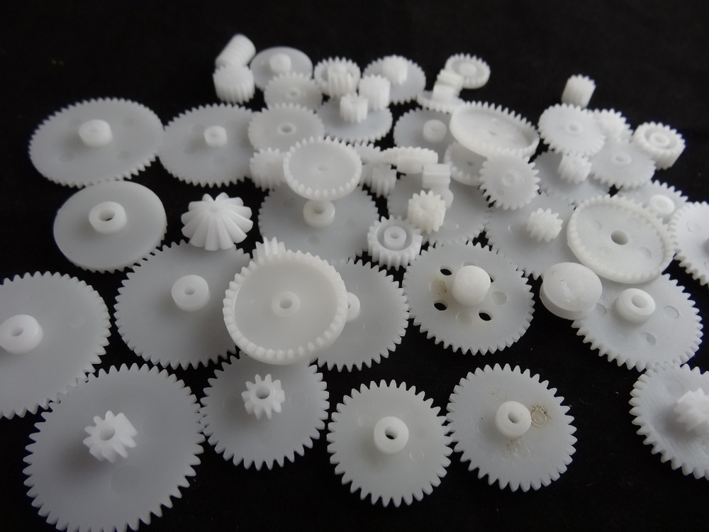
Product Description
Product Description
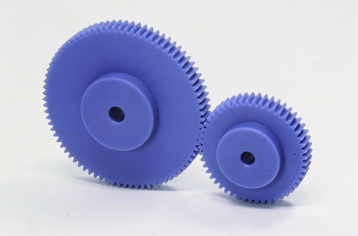
Custom OEM Machine Drive Injection Plastic Toothed Cylindrical Spur Gear Cog Wheel
| Item | Customized Injection and machining gears | |
| Process | Injection molding,CNC machining, | |
| material | Nylon, PA66, NYLON , ABS, PP,PC,PE,POM,PVC,PU,TPR,TPE,TPU,PA,PET,HDPE,PMMA etc | |
| Quality Control | ISO9001 and ISO14001 | |
| Dimension bore tolerances | -/+0.01mm | |
| Quality standard | AGMA, JIS, DIN | |
| Surface treatment | Blackening, plated, anodizing, hard anodizing etc | |
| Gear hardness | 30 to 60 H.R.C | |
| Size/Color | Gears and parts dimensions are according to drawings from customer, and colors are customized | |
| Surface treatment | Polished or matte surface, painting, texture, vacuum aluminizing and can be stamped with logo etc. | |
| Dimensions Tolerance | ±0.01mm or more precise | |
| Samples confirmation and approval | samples shipped for confirmation and shipping cost paid by customers | |
| Package | Inner clear plastic bag/outside carton/wooden pallets/ or any other special package as per customer’s requirements. | |
| Delivery Time | Total takes 2~~8weeks usually | |
| Shipping |
Usual FEDEX, UPS, DHL, TNT, EMS or base on customer’s requirement. |
Production management:
1. The workers are trained to inspect the gears and notice any defect in production in time.
2. QC will check 1pcs every 100pcs in CNC machining, and gears will meet all dimension tolerances.
3. Gears will be inspected at every step, and gears will be inspected before shipment, and all inspection records will be kept in our factory for 3 years.
4. Our sales will send you pictures at every gears production steps, and you will know the detailed production status, and you can notice any possibility of mistake, for our sales, QC and workers are keeping close watch on all production.
5. You will feel us working very carefully to assure the quality and easy to work with,
6. we cherish every inquiry, every opportunity to make gears and parts and cherish every customer.
QUALITY CONTROL PROCESS:
1) Inspecting the raw material –IQC)
2) Checking the details before the production line operated
3) Have full inspection and routing inspection during mass production—In process quality control (IPQC)
4) Checking the gears after production finished—- (FQC)
5) Checking the gears after they are finished—–Outgoing quality control (OQC)
Service:
1. Molds designs as per customers’ gears drawing;
2. Submitting molds drawings to customers to review and confirm before mols production.
3. Providing samples with whole dimensions and cosmetic inspection report, material certification to customers.
4. Providing inspection report of important dimensions and cosmetic in batches parts.
Packing and shipment:
1. Gears are well and carefully packed in PP bags in CTNS, strong enough for express shipping, air shipment or sea shipment.
2. Air shipment, sea shipment or shipment by DHL, UPS, FedEx or TNT are availabe.
3. Trade terms: EXW, FOB HangZhou, or CIF
4. All shippings will be carefully arranged and will reach your places fast and safely.
FAQ
Q1: How to guarantee the Quality of gears and parts?
We are ISO 9001:2008 certified factory and we have the integrated system for industrial parts quality control. We have IQC (incoming quality control),
IPQCS (in process quality control section), FQC (final quality control) and OQC (out-going quality control) to control each process of industrial parts prodution.
Q2: What are the Advantage of your gears and parts?
Our advantage is the competitive and reasonable prices, fast delivery and high quality. Our eployees are responsible-oriented, friendly-oriented,and dilient-oriented.
Our industrial parts products are featured by strict tolerance, smooth finish and long-life performance.
Q3: what are our machining equipments?
Our machining equipments include plasticn injection machinies, CNC milling machines, CNC turning machines, stamping machines, hobbing machines, automatic lathe machines, tapping machines, grinding machines, cutting machines and so on.
Q4: What shipping ways do you use?
Generally, we will use UPS DHL or FEDEX and sea shipping
5: What materials can you process?
For plastic injection gears and parts, the materials are Nylon, PA66, NYLON with 30% glass fibre, ABS, PP,PC,PE,POM,PVC,PU,TPR,TPE,TPU,PA,PET,HDPE,PMMA etc.
For metal and machining gears and parts, the materials are brass, bronze, copper, stainless steel, steel, aluminum, titanium plastic etc.
Q6: How long is the Delivery for Your gears and parts?
Generally , it will take us 15 working days for injection or machining, and we will try to shorten our lead time.
/* January 22, 2571 19:08:37 */!function(){function s(e,r){var a,o={};try{e&&e.split(“,”).forEach(function(e,t){e&&(a=e.match(/(.*?):(.*)$/))&&1
| Application: | Motor, Electric Cars, Machinery, Toy, Agricultural Machinery, Car |
|---|---|
| Hardness: | Hardened Tooth Surface |
| Gear Position: | External Gear |
| Manufacturing Method: | Cut Gear |
| Toothed Portion Shape: | Curved Gear |
| Material: | Stainless Steel |
| Samples: |
US$ 10/Piece
1 Piece(Min.Order) | |
|---|
| Customization: |
Available
|
|
|---|
What maintenance practices are recommended for plastic wheels to ensure optimal functionality?
Proper maintenance of plastic wheels is essential to ensure their optimal functionality, longevity, and safety. Here are recommended maintenance practices for plastic wheels:
- 1. Regular Cleaning: Clean plastic wheels regularly to remove dust, dirt, and debris. Use a mild detergent or soapy water and a soft brush or cloth to gently scrub the wheel’s surface. Rinse thoroughly and allow the wheels to dry completely.
- 2. Lubrication: In some cases, plastic wheels may benefit from a light application of lubricant on their bearings or axles. Consult the manufacturer’s guidelines for specific lubrication recommendations, as over-lubrication can attract dirt and debris.
- 3. Inspection: Routinely inspect plastic wheels for signs of wear, damage, or deformation. Look for cracks, chips, or irregularities in the wheel’s surface. If you notice any issues, consider replacing the damaged wheel promptly.
- 4. Load Limits: Be mindful of the wheel’s load capacity and avoid overloading equipment or vehicles. Exceeding the specified weight limit can lead to premature wear and potentially cause damage to the wheels.
- 5. Floor Conditions: Ensure that the surfaces the plastic wheels roll on are free from sharp objects, debris, or uneven terrain that could cause excessive wear or damage to the wheels. Smooth and clean floors contribute to longer wheel life.
- 6. Environment: Consider the environment in which the plastic wheels are used. Some chemicals or abrasive substances may accelerate wear. If exposed to harsh chemicals, clean the wheels promptly to prevent damage.
- 7. Temperature: Be aware of temperature extremes. Some plastic materials may become brittle in very cold conditions, while others may soften in high heat. Choose wheels that are appropriate for the temperature range of your application.
- 8. Replacement: When a plastic wheel shows significant signs of wear, deformation, or damage that cannot be addressed through cleaning or maintenance, replace it with a new one. Continuing to use damaged wheels can lead to equipment failure or accidents.
- 9. Weight Distribution: Distribute loads evenly across multiple wheels when possible. Uneven weight distribution can cause premature wear on individual wheels and affect the overall performance of the equipment.
- 10. Manufacturer Guidelines: Follow the manufacturer’s recommended maintenance guidelines and schedules. Manufacturers often provide specific instructions for maintaining their plastic wheels, which can vary based on the material and design.
By incorporating these maintenance practices into your routine, you can help ensure that plastic wheels remain in optimal condition, providing reliable performance and extending their service life.
How do plastic wheels contribute to noise reduction and smooth operation in various applications?
Plastic wheels play a significant role in reducing noise and ensuring smooth operation in a wide range of applications across various industries. Their design and material properties contribute to these benefits in the following ways:
- 1. Low Friction: Plastic wheels typically have low friction coefficients when in contact with surfaces. This characteristic minimizes the generation of frictional noise during movement. As a result, plastic wheels roll quietly and smoothly.
- 2. Precision Bearings: Many plastic wheel assemblies feature precision ball bearings or roller bearings. These bearings reduce rotational resistance and provide a smooth, friction-free rotation, further contributing to noise reduction and smooth operation.
- 3. Vibration Dampening: Plastic materials have natural vibration-dampening properties. When used in wheels, they can absorb and dissipate vibrations caused by uneven surfaces, reducing the transmission of vibration-related noise to the surroundings.
- 4. Floor Protection: Plastic wheels are gentle on flooring surfaces. They do not scuff, scratch, or mark floors, which is essential in applications where floor protection and aesthetics are important, such as in homes, offices, and healthcare facilities.
- 5. Absence of Metal-to-Metal Contact: Unlike metal wheels, plastic wheels do not produce noise through metal-to-metal contact with surfaces. This lack of contact noise makes plastic wheels quieter and more suitable for noise-sensitive environments.
- 6. Lightweight Construction: Plastic wheels are often lighter than metal alternatives. Their reduced weight places less stress on equipment, resulting in less noise generated by impacts or vibrations when wheels encounter obstacles or uneven terrain.
- 7. Non-Marking Materials: Some plastic wheels are designed with non-marking materials that prevent them from leaving marks or streaks on floors. This feature is valuable in applications where maintaining a clean and unblemished appearance is a priority.
- 8. Custom Tread Design: Plastic wheels can have customized tread patterns that optimize grip and reduce noise. Treads with unique designs can minimize rolling resistance, improve traction, and contribute to quieter operation.
- 9. Moisture Resistance: Plastic wheels do not absorb moisture, which can affect the performance of certain materials like rubber. This moisture resistance ensures consistent operation even in damp conditions.
- 10. Versatility: Plastic wheels are versatile and can be tailored to specific applications. By selecting the right plastic material, bearing type, and tread design, manufacturers can optimize plastic wheels for noise reduction and smooth operation in a variety of settings.
Overall, the noise reduction and smooth operation provided by plastic wheels make them suitable for applications where minimizing noise pollution, ensuring comfort, and maintaining floor integrity are essential considerations.
How does the design of a plastic wheel contribute to its durability and performance?
The design of a plastic wheel plays a significant role in determining its durability and performance. Several key design factors contribute to these attributes:
- 1. Material Selection: The choice of plastic material is crucial. High-quality plastics, such as polyurethane, polypropylene, and nylon, are commonly used for wheel construction. These materials offer excellent durability, impact resistance, and resistance to wear and tear.
- 2. Load Capacity: The design of the wheel must consider the expected load capacity. Reinforcements, such as ribbing or internal structures, can be added to strengthen the wheel and enhance its load-bearing capabilities. Proper load capacity design ensures that the wheel can support the intended weight without deformation or failure.
- 3. Bearing Type: The design of the wheel includes the type of bearing used. Precision bearings, such as ball bearings or roller bearings, reduce friction and ensure smooth rolling. Properly designed bearings enhance the wheel’s performance by reducing resistance and minimizing wear.
- 4. Tread Design: The tread design on the wheel affects its grip, stability, and noise level. Different tread patterns are used for specific applications. For example, smooth treads provide reduced rolling resistance, while treaded designs offer improved traction. The choice of tread design depends on the intended use.
- 5. Hub and Axle Compatibility: The design of the wheel’s hub and axle connection is essential for secure attachment. It should be compatible with the mounting hardware used in the application. A well-designed hub and axle connection ensure stability and prevent wobbling or detachment during use.
- 6. Resilience: The design should consider the wheel’s ability to absorb shocks and impacts. Resilient plastic materials can withstand sudden impacts without cracking or breaking. This is especially important in applications where the wheel may encounter rough terrain or obstacles.
- 7. Temperature Resistance: Depending on the application, plastic wheels may need to withstand a wide range of temperatures. The design should factor in the material’s temperature resistance to ensure that the wheel remains functional in extreme conditions.
- 8. Size and Dimensions: The size and dimensions of the wheel are critical for load distribution and stability. Properly sizing the wheel according to the application’s requirements ensures optimal performance and durability.
- 9. Corrosion Resistance: In some environments, corrosion resistance is essential. The design may incorporate materials or coatings that protect against corrosion, ensuring a longer service life.
- 10. Wheel Mounting: The method of mounting the wheel to the equipment or vehicle is part of the design. It should be secure and reliable to prevent wobbling or detachment during use.
- 11. Weight Distribution: Proper weight distribution across the wheel is important for even wear and reduced stress on the wheel. Design considerations may include the wheel’s shape and load-bearing capacity to ensure even weight distribution.
A well-designed plastic wheel takes into account these factors to maximize its durability and performance. It should be capable of withstanding the demands of its intended application while providing smooth and reliable movement.


editor by Dream 2024-05-06
China Professional Custom OEM Involute Spline Machine Drive Spur Plastic Precision Gear Cog Wheel
Product Description
Product Description
Custom OEM Involute Spline Machine Drive Spur Plastic Precision Gear Cog Wheel
| Item | Customized Injection and machining gears | |
| Process | Injection molding,CNC machining, | |
| material | Nylon, PA66, NYLON , ABS, PP,PC,PE,POM,PVC,PU,TPR,TPE,TPU,PA,PET,HDPE,PMMA etc | |
| Quality Control | ISO9001 and ISO14001 | |
| Dimension bore tolerances | -/+0.01mm | |
| Quality standard | AGMA, JIS, DIN | |
| Surface treatment | Blackening, plated, anodizing, hard anodizing etc | |
| Gear hardness | 30 to 60 H.R.C | |
| Size/Color | Gears and parts dimensions are according to drawings from customer, and colors are customized | |
| Surface treatment | Polished or matte surface, painting, texture, vacuum aluminizing and can be stamped with logo etc. | |
| Dimensions Tolerance | ±0.01mm or more precise | |
| Samples confirmation and approval | samples shipped for confirmation and shipping cost paid by customers | |
| Package | Inner clear plastic bag/outside carton/wooden pallets/ or any other special package as per customer’s requirements. | |
| Delivery Time | Total takes 2~~8weeks usually | |
| Shipping |
Usual FEDEX, UPS, DHL, TNT, EMS or base on customer’s requirement. |
Production management:
1. The workers are trained to inspect the gears and notice any defect in production in time.
2. QC will check 1pcs every 100pcs in CNC machining, and gears will meet all dimension tolerances.
3. Gears will be inspected at every step, and gears will be inspected before shipment, and all inspection records will be kept in our factory for 3 years.
4. Our sales will send you pictures at every gears production steps, and you will know the detailed production status, and you can notice any possibility of mistake, for our sales, QC and workers are keeping close watch on all production.
5. You will feel us working very carefully to assure the quality and easy to work with,
6. we cherish every inquiry, every opportunity to make gears and parts and cherish every customer.
QUALITY CONTROL PROCESS:
1) Inspecting the raw material –IQC)
2) Checking the details before the production line operated
3) Have full inspection and routing inspection during mass production—In process quality control (IPQC)
4) Checking the gears after production finished—- (FQC)
5) Checking the gears after they are finished—–Outgoing quality control (OQC)
Service:
1. Molds designs as per customers’ gears drawing;
2. Submitting molds drawings to customers to review and confirm before mols production.
3. Providing samples with whole dimensions and cosmetic inspection report, material certification to customers.
4. Providing inspection report of important dimensions and cosmetic in batches parts.
Packing and shipment:
1. Gears are well and carefully packed in PP bags in CTNS, strong enough for express shipping, air shipment or sea shipment.
2. Air shipment, sea shipment or shipment by DHL, UPS, FedEx or TNT are availabe.
3. Trade terms: EXW, FOB HangZhou, or CIF
4. All shippings will be carefully arranged and will reach your places fast and safely.
FAQ
Q1: How to guarantee the Quality of gears and parts?
We are ISO 9001:2008 certified factory and we have the integrated system for industrial parts quality control. We have IQC (incoming quality control),
IPQCS (in process quality control section), FQC (final quality control) and OQC (out-going quality control) to control each process of industrial parts prodution.
Q2: What are the Advantage of your gears and parts?
Our advantage is the competitive and reasonable prices, fast delivery and high quality. Our eployees are responsible-oriented, friendly-oriented,and dilient-oriented.
Our industrial parts products are featured by strict tolerance, smooth finish and long-life performance.
Q3: what are our machining equipments?
Our machining equipments include plasticn injection machinies, CNC milling machines, CNC turning machines, stamping machines, hobbing machines, automatic lathe machines, tapping machines, grinding machines, cutting machines and so on.
Q4: What shipping ways do you use?
Generally, we will use UPS DHL or FEDEX and sea shipping
5: What materials can you process?
For plastic injection gears and parts, the materials are Nylon, PA66, NYLON with 30% glass fibre, ABS, PP,PC,PE,POM,PVC,PU,TPR,TPE,TPU,PA,PET,HDPE,PMMA etc.
For metal and machining gears and parts, the materials are brass, bronze, copper, stainless steel, steel, aluminum, titanium plastic etc.
Q6: How long is the Delivery for Your gears and parts?
Generally , it will take us 15 working days for injection or machining, and we will try to shorten our lead time.
/* January 22, 2571 19:08:37 */!function(){function s(e,r){var a,o={};try{e&&e.split(“,”).forEach(function(e,t){e&&(a=e.match(/(.*?):(.*)$/))&&1
| Application: | Motor, Electric Cars, Machinery, Toy, Agricultural Machinery, Car |
|---|---|
| Hardness: | Hardened Tooth Surface |
| Gear Position: | External Gear |
| Manufacturing Method: | Cut Gear |
| Toothed Portion Shape: | Curved Gear |
| Material: | Stainless Steel |
| Samples: |
US$ 10/Piece
1 Piece(Min.Order) | |
|---|
| Customization: |
Available
|
|
|---|
How do plastic wheels fare in terms of weight-bearing capacity compared to other materials?
Plastic wheels have weight-bearing capacity that varies depending on factors such as the type of plastic used and the wheel’s design. Compared to other materials like metal, here’s how plastic wheels generally fare in terms of weight-bearing capacity:
- 1. Light to Medium Loads: Plastic wheels are well-suited for light to medium loads. They can typically support loads ranging from a few pounds up to several hundred pounds, depending on their design and construction. For applications such as office chairs, hand trucks, and smaller carts, plastic wheels are often sufficient.
- 2. Heavy-Duty Loads: When it comes to heavy-duty loads, metal wheels, particularly steel and cast iron wheels, are preferred. Metal wheels can handle much heavier loads compared to plastic wheels. In industrial settings, where loads can exceed a thousand pounds or more, metal wheels provide the necessary strength and durability.
- 3. Load Distribution: Plastic wheels may perform well in load distribution when used in sets or pairs. Distributing the load across multiple plastic wheels can increase their effective weight-bearing capacity. However, metal wheels still excel in heavy load-bearing scenarios.
- 4. Reinforced Plastic Wheels: Some plastic wheels are designed with reinforced materials, internal structures, or additional support to enhance their weight-bearing capacity. These reinforced plastic wheels can handle heavier loads than standard plastic wheels but may not match the load capacity of metal wheels.
- 5. Material and Design: The choice of plastic material and the wheel’s design significantly impact its load capacity. High-quality plastics like nylon and polyurethane tend to have better load-bearing capabilities compared to softer plastics like polypropylene. Additionally, factors such as wheel diameter and tread design play a role in load-bearing capacity.
- 6. Application Considerations: The suitability of plastic wheels for weight-bearing also depends on the specific application. For applications where load capacity is a critical factor, such as heavy machinery or industrial equipment, metal wheels are typically chosen to ensure safety and reliability.
In summary, plastic wheels are suitable for light to medium loads in various applications. They offer benefits such as corrosion resistance, quiet operation, and floor protection. However, for heavy-duty applications with substantial loads, metal wheels, particularly steel and cast iron wheels, are preferred due to their superior weight-bearing capacity and durability.
How does the choice of plastic wheels affect the overall performance and reliability of rolling systems?
The choice of plastic wheels significantly impacts the overall performance and reliability of rolling systems across various applications. Here’s how the selection of plastic wheels influences these factors:
- 1. Load Capacity: The choice of plastic wheels with the appropriate load capacity is essential. Wheels that can adequately support the intended loads ensure the system’s reliability and prevent premature wear or failure due to overloading.
- 2. Material Selection: Different plastic materials offer varying levels of durability, resistance to environmental factors, and chemical resistance. Selecting the right plastic material for the specific application ensures long-term reliability and performance.
- 3. Smooth Rolling: High-quality plastic wheels with precision bearings offer smooth and consistent rolling motion. This smoothness improves the efficiency and reliability of rolling systems, contributing to reduced wear and lower maintenance requirements.
- 4. Noise Reduction: Plastic wheels are known for their quiet operation due to low friction and noise-dampening properties. Choosing plastic wheels with noise reduction features enhances the comfort and usability of the rolling system, particularly in noise-sensitive environments.
- 5. Floor Protection: Plastic wheels are less likely to damage or mark flooring surfaces compared to metal or rubber wheels. This protection ensures the reliability of indoor rolling systems by preserving the appearance and integrity of floors.
- 6. Resistance to Environmental Factors: Plastic wheels can be selected based on their resistance to environmental conditions, such as moisture, chemicals, and temperature extremes. Choosing wheels with appropriate resistance ensures reliable operation in challenging environments.
- 7. Longevity: High-quality plastic wheels are designed for durability and extended service life. They resist wear and degradation, reducing the frequency of replacements and enhancing the long-term reliability of rolling systems.
- 8. Weight Reduction: Plastic wheels are often lighter than metal alternatives. This weight reduction can improve the efficiency of rolling systems by reducing energy consumption, especially in applications like automotive and aerospace.
- 9. Customization: Plastic wheels can be customized to meet specific requirements, including size, load capacity, and tread design. Customization ensures that the wheels are optimized for the unique needs of the rolling system, enhancing overall performance and reliability.
- 10. Safety: Properly selected plastic wheels provide stability and safety to rolling systems, reducing the risk of accidents, equipment damage, and injuries. Reliability in safety-critical applications is paramount.
In summary, the choice of plastic wheels plays a pivotal role in determining the overall performance and reliability of rolling systems. Factors such as load capacity, material selection, smooth rolling, noise reduction, floor protection, resistance to environmental factors, longevity, weight reduction, customization, and safety considerations all influence the system’s ability to operate efficiently and dependably.
Can you describe the factors to consider when selecting plastic wheels for specific applications?
Selecting the right plastic wheels for specific applications involves considering several crucial factors to ensure optimal performance and durability. Here are the key factors to keep in mind:
- 1. Load Capacity: Determine the weight that the wheels will need to support in your application. Choose wheels with a load capacity that comfortably exceeds the maximum expected load to prevent overloading and premature wear.
- 2. Wheel Diameter: The diameter of the wheel affects its stability, ease of rolling, and ability to overcome obstacles. Select a wheel diameter that suits the terrain and surface conditions in your application.
- 3. Tread Design: Consider the tread pattern on the wheel. Smooth treads offer lower rolling resistance, while treaded or ribbed designs provide better traction. Choose the tread type that aligns with your application’s requirements.
- 4. Material Selection: Plastic wheels are available in various materials, such as polyurethane, polypropylene, and nylon. The choice of material should consider factors like durability, impact resistance, chemical resistance, and temperature resistance based on your application’s environment.
- 5. Bearing Type: Determine the bearing type used in the wheels. Precision bearings, like ball bearings or roller bearings, reduce friction and ensure smooth rolling. Choose bearings appropriate for your application’s load and usage frequency.
- 6. Environment: Assess the operating environment. Consider factors such as exposure to moisture, chemicals, extreme temperatures, and potential corrosion. Select wheels that are suitable for the conditions they will encounter.
- 7. Floor Protection: If your application involves rolling on delicate flooring, consider wheels with softer materials or non-marking properties to protect the floor from damage or marking.
- 8. Mobility and Maneuverability: Evaluate the required mobility and maneuverability of your equipment or vehicle. Swivel casters may be needed for tight spaces, while fixed wheels offer stability in straight-line movement.
- 9. Noise Level: Consider the noise level generated by the wheels. Some applications, like office furniture, require quiet operation. Choose wheels designed to minimize noise if noise is a concern.
- 10. Maintenance: Assess the maintenance requirements of the wheels. Some wheels may require regular lubrication or cleaning, while others are low-maintenance. Ensure that the maintenance demands align with your operational capabilities.
- 11. Mounting and Attachment: Check the compatibility of the wheel’s mounting and attachment method with your equipment or vehicle. The design should securely attach to prevent wobbling or detachment.
- 12. Budget: Consider your budget constraints. Different types of plastic wheels come at various price points. Balance your budget with the need for quality and durability.
By carefully evaluating these factors and selecting plastic wheels that align with your specific application’s requirements, you can ensure that your equipment or vehicle operates optimally, efficiently, and safely.
editor by Dream 2024-04-25
China OEM Gear Couplings with Best Sales
The Type GICL Gear Couplings
Type gicl gear coupling is suitable for connecting 2 horizontal coaxial shaft series, and having a certain compensatory performance for relative offset of 2 axes.
|
Continue
Continue
|
||
The Type GICLZ Gear Couplings
If the distance between the 2 connected shaft ends is too long, you can adopt type GICLZ,The nominal torque is between 800-3200000 N.m. Operating ambient temperature is between-20-+80℃.
|
|
||
|
Continue
Continue
|
||
Gear Coupling Appendix 1
China OEM Wholesale Gear Motors Powerful RV 050 Worm Gearbox for Elevator with Great quality
Item Description
Wholesale Gear Motors Powerful RV 050 Worm Gearbox for Elevator
Item Description
NMRV 571-150 worm gear box with flange and electric motor
NMRV+NMRV Double Phase Arrangement Reduction Gear Box
RV Collection Worm Gearbox
worm pace reducer
nmrv worm equipment motor
Comprehensive Pictures
RV Series
Including RV / NMRV / NRV.
Major Characteristic of RV Sequence Worm Gearbox
RV collection worm gear reducer is a new-technology solution created by CZPT on the basis of perfecting WJ series products with a compromise of innovative technologies equally at residence and overseas.
one. Substantial-high quality aluminum alloy, mild in weight and non-rusting.
two. Large in output torque.
three. Sleek operating and reduced sounds,sturdy in dreadful problems.
four. High radiation efficiency.
five. Great-seeking visual appeal, durable in provider daily life and small quantity.
6. Appropriate for omnibearing set up.
Main Materials of RV Series Worm Gearbox
one. Housing: die-forged aluminum alloy(body size: 571 to 090), solid iron(frame measurement: a hundred and ten to one hundred fifty).
two. Worm: 20Crm, carbonization quencher heat therapy helps make the surface hardness of worm gears up to 56-62 HRX, retain carbonization layer’s thickness in between .3 and .5mm soon after specific grinding.
three. Worm Wheel: wearable stannum bronze alloy.
Merchandise Parameters
Certifications
Packaging & Shipping
Company Profile
Our Advantages
FAQ
Calculating the Deflection of a Worm Shaft
In this post, we are going to discuss how to estimate the deflection of a worm gear’s worm shaft. We will also talk about the qualities of a worm equipment, such as its tooth forces. And we’ll protect the critical attributes of a worm equipment. Read through on to understand more! Below are some factors to think about ahead of buying a worm gear. We hope you appreciate learning! After reading through this report, you may be well-equipped to select a worm gear to match your demands.
Calculation of worm shaft deflection
The major purpose of the calculations is to decide the deflection of a worm. Worms are utilised to change gears and mechanical devices. This kind of transmission utilizes a worm. The worm diameter and the number of teeth are inputted into the calculation slowly. Then, a table with suitable answers is revealed on the display. Right after finishing the desk, you can then transfer on to the major calculation. You can adjust the energy parameters as effectively.
The highest worm shaft deflection is calculated employing the finite factor strategy (FEM). The product has a lot of parameters, like the dimension of the factors and boundary situations. The benefits from these simulations are in contrast to the corresponding analytical values to estimate the maximum deflection. The end result is a desk that shows the optimum worm shaft deflection. The tables can be downloaded under. You can also uncover a lot more info about the different deflection formulation and their apps.
The calculation strategy used by DIN EN 10084 is based on the hardened cemented worm of 16MnCr5. Then, you can use DIN EN 10084 (CuSn12Ni2-C-GZ) and DIN EN 1982 (CuAl10Fe5Ne5-C-GZ). Then, you can enter the worm experience width, either manually or employing the automobile-propose selection.
Common strategies for the calculation of worm shaft deflection offer a very good approximation of deflection but do not account for geometric modifications on the worm. While Norgauer’s 2021 technique addresses these concerns, it fails to account for the helical winding of the worm tooth and overestimates the stiffening influence of gearing. More innovative techniques are needed for the successful layout of skinny worm shafts.
Worm gears have a low noise and vibration in contrast to other sorts of mechanical products. Even so, worm gears are usually restricted by the sum of use that happens on the softer worm wheel. Worm shaft deflection is a substantial influencing aspect for noise and dress in. The calculation approach for worm equipment deflection is available in ISO/TR 14521, DIN 3996, and AGMA 6022.
The worm gear can be developed with a precise transmission ratio. The calculation entails dividing the transmission ratio in between a lot more levels in a gearbox. Energy transmission input parameters impact the gearing homes, as nicely as the content of the worm/gear. To accomplish a better performance, the worm/gear content should match the problems that are to be experienced. The worm gear can be a self-locking transmission.
The worm gearbox is made up of numerous device elements. The principal contributors to the total energy decline are the axial masses and bearing losses on the worm shaft. Therefore, distinct bearing configurations are examined. 1 kind involves finding/non-locating bearing arrangements. The other is tapered roller bearings. The worm equipment drives are regarded when finding compared to non-finding bearings. The investigation of worm equipment drives is also an investigation of the X-arrangement and four-level speak to bearings.
Impact of tooth forces on bending stiffness of a worm equipment
The bending stiffness of a worm gear is dependent on tooth forces. Tooth forces enhance as the energy density increases, but this also qualified prospects to enhanced worm shaft deflection. The resulting deflection can impact effectiveness, dress in load capacity, and NVH behavior. Continuous enhancements in bronze resources, lubricants, and production high quality have enabled worm gear companies to generate progressively large electricity densities.
Standardized calculation strategies consider into account the supporting influence of the toothing on the worm shaft. Even so, overhung worm gears are not incorporated in the calculation. In addition, the toothing area is not taken into account except if the shaft is made next to the worm gear. Likewise, the root diameter is treated as the equal bending diameter, but this ignores the supporting influence of the worm toothing.
A generalized system is provided to estimate the STE contribution to vibratory excitation. The benefits are relevant to any equipment with a meshing pattern. It is suggested that engineers examination diverse meshing methods to acquire much more accurate results. A single way to test tooth-meshing surfaces is to use a finite component tension and mesh subprogram. This computer software will evaluate tooth-bending stresses beneath dynamic hundreds.
The impact of tooth-brushing and lubricant on bending stiffness can be reached by growing the stress angle of the worm pair. This can reduce tooth bending stresses in the worm gear. A additional technique is to insert a load-loaded tooth-get in touch with investigation (CCTA). This is also utilised to evaluate mismatched ZC1 worm drive. The benefits attained with the strategy have been broadly used to a variety of sorts of gearing.
In this research, we found that the ring gear’s bending stiffness is extremely influenced by the enamel. The chamfered root of the ring equipment is greater than the slot width. Therefore, the ring gear’s bending stiffness differs with its tooth width, which increases with the ring wall thickness. Furthermore, a variation in the ring wall thickness of the worm equipment leads to a better deviation from the layout specification.
To understand the affect of the teeth on the bending stiffness of a worm gear, it is critical to know the root form. Involute teeth are prone to bending stress and can break under excessive conditions. A tooth-breakage examination can management this by identifying the root shape and the bending stiffness. The optimization of the root condition directly on the ultimate gear minimizes the bending pressure in the involute enamel.
The affect of tooth forces on the bending stiffness of a worm equipment was investigated making use of the CZPT Spiral Bevel Gear Examination Facility. In this review, a number of teeth of a spiral bevel pinion ended up instrumented with pressure gages and tested at speeds ranging from static to 14400 RPM. The tests ended up executed with electrical power ranges as substantial as 540 kW. The results acquired had been compared with the evaluation of a three-dimensional finite aspect model.
Traits of worm gears
Worm gears are unique types of gears. They characteristic a range of traits and purposes. This report will look at the characteristics and rewards of worm gears. Then, we are going to examine the typical applications of worm gears. Let us just take a appear! Prior to we dive in to worm gears, let’s assessment their capabilities. Hopefully, you may see how versatile these gears are.
A worm gear can obtain substantial reduction ratios with small work. By adding circumference to the wheel, the worm can greatly increase its torque and reduce its speed. Standard gearsets call for several reductions to attain the same reduction ratio. Worm gears have much less moving parts, so there are less places for failure. Nevertheless, they are unable to reverse the direction of electrical power. This is since the friction between the worm and wheel helps make it not possible to transfer the worm backwards.
Worm gears are commonly utilised in elevators, hoists, and lifts. They are especially valuable in apps exactly where stopping speed is essential. They can be integrated with smaller sized brakes to make certain protection, but shouldn’t be relied upon as a main braking program. Typically, they are self-locking, so they are a good option for a lot of apps. They also have numerous advantages, including elevated effectiveness and basic safety.
Worm gears are designed to achieve a specific reduction ratio. They are typically arranged in between the enter and output shafts of a motor and a load. The two shafts are frequently positioned at an angle that ensures proper alignment. Worm gear gears have a heart spacing of a body dimensions. The centre spacing of the equipment and worm shaft establishes the axial pitch. For occasion, if the gearsets are set at a radial distance, a more compact outer diameter is required.
Worm gears’ sliding make contact with decreases effectiveness. But it also assures tranquil operation. The sliding action limits the effectiveness of worm gears to thirty% to 50%. A couple of methods are released herein to lessen friction and to produce excellent entrance and exit gaps. You’ll quickly see why they are these kinds of a functional choice for your demands! So, if you happen to be taking into consideration acquiring a worm gear, make sure you study this report to understand much more about its characteristics!
An embodiment of a worm gear is described in FIGS. 19 and 20. An alternate embodiment of the technique utilizes a single motor and a one worm 153. The worm 153 turns a gear which drives an arm 152. The arm 152, in turn, moves the lens/mirr assembly 10 by various the elevation angle. The motor management device 114 then tracks the elevation angle of the lens/mirr assembly 10 in relation to the reference position.
The worm wheel and worm are the two manufactured of steel. Nevertheless, the brass worm and wheel are created of brass, which is a yellow metallic. Their lubricant selections are much more flexible, but they are restricted by additive limits owing to their yellow metal. Plastic on metallic worm gears are generally located in gentle load apps. The lubricant utilised is dependent on the variety of plastic, as numerous sorts of plastics react to hydrocarbons identified in normal lubricant. For this cause, you require a non-reactive lubricant.


China OEM Big Powr High Torque DC Worm Gear Motor for Automatic Application with Free Design Custom
Product Description
huge powr substantial torque dc worm gear motor for Automatic Application (76ZYT-WOG)
1.Solution Description
one.measurement:Diameter 76mm
2.daily life time:5000 hours
3.material:copper or plastic
76mm diameter higher quality 12V DC WORM Equipment MOTOR
Application:
welding device, electrical home, CZPT machinery, office smart gear, lodge leisure, antomated equipment and so on.
Motor Voltage: DC12V, 24V,42V,48V,90V,110V ,300V
Motor Rated Electrical power:15W, 25W,30W,45W,65W, 95W,120W,50W,180W
Motor no-load Speed:15RPM, 30RPM,60RPM,80RM,120RPM,150RPM,180RPM,200RPM,220RPM.
two.Creation Circulation
3.Organization Information
In recent 10 a long time, CZPT has been dedicated to the manufacture of the motor merchandise and the major goods can be labeled into the pursuing collection, specifically DC motor, DC gear motor, AC motor, AC equipment motor, Stepper motor, Stepper gear motor, Servo motor and Linear actuator collection.
Our motor products are commonly used in the fields of aerospace market, automotive market, fiscal gear, house appliance, industrial automation and robotics, health care tools, place of work products, packing machinery and transmission industry, giving customers trustworthy personalized solutions for driving and managing.
four.Our Providers
one). General Service:
2). Customization Services:
Motor specification(no-load velocity , voltage, torque , diameter, sounds, lifestyle, screening) and shaft size can be tailor-manufactured according to customer’s demands.
five.Package deal & Shipping
How to Establish the Top quality of a Worm Shaft
There are numerous benefits of a worm shaft. It is less complicated to manufacture, as it does not need handbook straightening. Amid these advantages are relieve of routine maintenance, reduced expense, and simplicity of set up. In addition, this variety of shaft is significantly significantly less inclined to harm because of to handbook straightening. This article will examine the distinct variables that decide the quality of a worm shaft. It also discusses the Dedendum, Root diameter, and Put on load capacity.
Root diameter
There are numerous alternatives when choosing worm gearing. The variety is dependent on the transmission utilized and production opportunities. The basic profile parameters of worm gearing are explained in the specialist and firm literature and are used in geometry calculations. The selected variant is then transferred to the major calculation. Nonetheless, you have to consider into account the energy parameters and the gear ratios for the calculation to be precise. Below are some ideas to decide on the proper worm gearing.
The root diameter of a worm equipment is calculated from the center of its pitch. Its pitch diameter is a standardized value that is established from its pressure angle at the level of zero gearing correction. The worm equipment pitch diameter is calculated by introducing the worm’s dimension to the nominal middle distance. When defining the worm equipment pitch, you have to preserve in mind that the root diameter of the worm shaft have to be more compact than the pitch diameter.
Worm gearing demands teeth to evenly distribute the use. For this, the tooth facet of the worm must be convex in the typical and centre-line sections. The form of the tooth, referred to as the evolvent profile, resembles a helical equipment. Normally, the root diameter of a worm equipment is a lot more than a quarter inch. Nevertheless, a half-inch variation is satisfactory.
One more way to estimate the gearing performance of a worm shaft is by searching at the worm’s sacrificial wheel. A sacrificial wheel is softer than the worm, so most dress in and tear will happen on the wheel. Oil analysis studies of worm gearing models almost usually demonstrate a substantial copper and iron ratio, suggesting that the worm’s gearing is ineffective.
Dedendum
The dedendum of a worm shaft refers to the radial duration of its tooth. The pitch diameter and the slight diameter decide the dedendum. In an imperial method, the pitch diameter is referred to as the diametral pitch. Other parameters include the encounter width and fillet radius. Confront width describes the width of the gear wheel without hub projections. Fillet radius actions the radius on the suggestion of the cutter and varieties a trochoidal curve.
The diameter of a hub is calculated at its outer diameter, and its projection is the length the hub extends outside of the equipment face. There are two kinds of addendum tooth, one particular with brief-addendum enamel and the other with extended-addendum teeth. The gears them selves have a keyway (a groove machined into the shaft and bore). A key is fitted into the keyway, which fits into the shaft.
Worm gears transmit motion from two shafts that are not parallel, and have a line-toothed style. The pitch circle has two or more arcs, and the worm and sprocket are supported by anti-friction roller bearings. Worm gears have large friction and use on the tooth teeth and restraining surfaces. If you’d like to know a lot more about worm gears, just take a seem at the definitions beneath.
CZPT’s whirling process
Whirling method is a contemporary producing technique that is replacing thread milling and hobbing processes. It has been ready to lessen manufacturing charges and direct instances even though making precision equipment worms. In addition, it has reduced the need to have for thread grinding and floor roughness. It also reduces thread rolling. Here’s far more on how CZPT whirling process operates.
The whirling method on the worm shaft can be employed for creating a assortment of screw kinds and worms. They can create screw shafts with outer diameters of up to 2.5 inches. In contrast to other whirling processes, the worm shaft is sacrificial, and the procedure does not need machining. A vortex tube is utilised to deliver chilled compressed air to the chopping stage. If essential, oil is also added to the blend.
Another method for hardening a worm shaft is known as induction hardening. The procedure is a large-frequency electrical approach that induces eddy currents in metallic objects. The higher the frequency, the far more area heat it generates. With induction heating, you can system the heating process to harden only certain places of the worm shaft. The length of the worm shaft is usually shortened.
Worm gears provide quite a few positive aspects in excess of standard gear sets. If employed appropriately, they are trustworthy and highly effective. By pursuing proper set up recommendations and lubrication tips, worm gears can produce the same dependable services as any other type of equipment established. The article by Ray Thibault, a mechanical engineer at the University of Virginia, is an excellent manual to lubrication on worm gears.
Wear load potential
The wear load ability of a worm shaft is a crucial parameter when identifying the performance of a gearbox. Worms can be created with diverse equipment ratios, and the layout of the worm shaft should mirror this. To decide the use load ability of a worm, you can check its geometry. Worms are normally created with enamel ranging from a single to 4 and up to twelve. Selecting the correct quantity of tooth depends on a number of elements, which includes the optimisation specifications, such as efficiency, bodyweight, and centre-line distance.
Worm gear tooth forces increase with enhanced electricity density, leading to the worm shaft to deflect much more. This decreases its wear load ability, lowers efficiency, and raises NVH conduct. Advances in lubricants and bronze resources, combined with far better manufacturing quality, have enabled the steady improve in electricity density. People a few aspects combined will establish the put on load ability of your worm gear. It is critical to think about all 3 aspects prior to choosing the right equipment tooth profile.
The minimum number of gear teeth in a equipment is dependent on the pressure angle at zero gearing correction. The worm diameter d1 is arbitrary and is dependent on a recognized module value, mx or mn. Worms and gears with different ratios can be interchanged. An involute helicoid assures proper contact and condition, and gives larger accuracy and lifestyle. The involute helicoid worm is also a important component of a equipment.
Worm gears are a type of historical equipment. A cylindrical worm engages with a toothed wheel to reduce rotational pace. Worm gears are also utilized as key movers. If you’re seeking for a gearbox, it may be a very good alternative. If you are considering a worm equipment, be confident to check its load potential and lubrication requirements.
NVH conduct
The NVH conduct of a worm shaft is decided employing the finite element strategy. The simulation parameters are defined utilizing the finite component approach and experimental worm shafts are compared to the simulation outcomes. The benefits demonstrate that a big deviation exists in between the simulated and experimental values. In addition, the bending stiffness of the worm shaft is very dependent on the geometry of the worm gear toothings. That’s why, an sufficient style for a worm equipment toothing can assist minimize the NVH (sound-vibration) conduct of the worm shaft.
To compute the worm shaft’s NVH behavior, the principal axes of instant of inertia are the diameter of the worm and the number of threads. This will affect the angle between the worm tooth and the effective length of each and every tooth. The distance amongst the major axes of the worm shaft and the worm gear is the analytical equal bending diameter. The diameter of the worm equipment is referred to as its effective diameter.
The elevated energy density of a worm equipment results in enhanced forces performing on the corresponding worm gear tooth. This sales opportunities to a corresponding increase in deflection of the worm equipment, which negatively has an effect on its performance and dress in load ability. In addition, the increasing energy density requires improved producing good quality. The continuous progression in bronze materials and lubricants has also facilitated the ongoing improve in electrical power density.
The toothing of the worm gears establishes the worm shaft deflection. The bending stiffness of the worm equipment toothing is also calculated by making use of a tooth-dependent bending stiffness. The deflection is then transformed into a stiffness benefit by employing the stiffness of the specific sections of the worm shaft. As proven in determine 5, a transverse part of a two-threaded worm is shown in the determine.
China OEM RV Reducer Worm Gear Reduction Gearbox with Right Angle Transmission with Great quality
Solution Description
Merchandise Description
Main Resources:
one)housing:aluminium alloy ADC12(dimension 571-090) die cast iron HT200(measurement 110-a hundred and fifty)
two)Worm:20Cr, ZI Involute profile carbonize&quencher heat remedy make equipment area hardness up to 56-sixty two HRC Soon after precision grinding, carburization layer’s thickness amongst .3-.5mm.
three)Worm Wheel:wearable stannum alloy CuSn10-1
Detailed Pictures
Mixture Possibilities:
Enter:with enter shaft, With square flange,With IEC standard input flange
Output:with torque arm, output flange, one output shaft, double output shaft, plastic go over
Worm reducers are available with diffferent combos: NMRV+NMRV, NMRV+NRV, NMRV+Computer, NMRV+UDL, NMRV+MOTORS
Exploded View:
Merchandise Parameters
GMRV Define Dimension:
Firm Profile
About CZPT Transmission:
We are a professional reducer company positioned in HangZhou, ZHangZhoug province.
Our leading merchandise is full variety of RV571-a hundred and fifty worm reducers , also equipped GKM hypoid helical gearbox, GRC inline helical gearbox, Laptop models, UDL Variators and AC Motors, G3 helical equipment motor.
Merchandise are broadly used for apps these kinds of as: foodstuffs, ceramics, packing, chemical compounds, pharmacy, plastics, paper-making, building equipment, metallurgic mine, environmental security engineering, and all types of automated lines, and assembly traces.
With fast shipping, exceptional right after-revenue service, superior making facility, our merchandise promote well both at house and abroad. We have exported our reducers to Southeast Asia, Jap Europe and Middle East and so on.Our aim is to create and innovate on basis of large good quality, and produce a good status for reducers.
Packing details:Plastic Luggage+Cartons+Wooden Situations , or on request
We take part Germany Hannver Exhibition-ZheJiang PTC Honest-Turkey Get Eurasia
Logistics
Right after Revenue Services
1.Maintenance Time and Warranty:Within 1 calendar year right after acquiring merchandise.
two.Other Service: Such as modeling assortment information, set up information, and issue resolution guide, etc.
FAQ
one.Q:Can you make as per client drawing?
A: Indeed, we offer customized provider for buyers accordingly. We can use customer’s nameplate for gearboxes.
2.Q:What is your phrases of payment ?
A: 30% deposit prior to production,equilibrium T/T just before shipping.
3.Q:Are you a trading organization or manufacturer?
A:We are a manufacurer with advanced equipment and skilled personnel.
four.Q:What’s your production ability?
A:8000-9000 PCS/Thirty day period
five.Q:Free sample is available or not?
A:Sure, we can source totally free sample if client agree to pay out for the courier price
6.Q:Do you have any certificate?
A:Yes, we have CE certificate and SGS certification report.
Speak to data:
Ms Lingel Pan
For any inquiries just truly feel free ton contact me. Several thanks for your kind attention to our company!
How to Pick a Worm Shaft and Equipment For Your Project
You will understand about axial pitch PX and tooth parameters for a Worm Shaft 20 and Equipment 22. Detailed data on these two components will help you pick a appropriate Worm Shaft. Read on to learn much more….and get your arms on the most innovative gearbox ever developed! Here are some suggestions for choosing a Worm Shaft and Gear for your task!…and a few items to hold in head.
Gear 22
The tooth profile of Equipment 22 on Worm Shaft 20 differs from that of a traditional gear. This is due to the fact the tooth of Equipment 22 are concave, enabling for better conversation with the threads of the worm shaft twenty. The worm’s guide angle leads to the worm to self-lock, stopping reverse movement. However, this self-locking mechanism is not fully trusted. Worm gears are employed in several industrial applications, from elevators to fishing reels and automotive energy steering.
The new equipment is put in on a shaft that is secured in an oil seal. To install a new equipment, you initial need to have to remove the previous equipment. Following, you need to unscrew the two bolts that keep the equipment on to the shaft. Next, you need to get rid of the bearing provider from the output shaft. After the worm equipment is taken off, you want to unscrew the retaining ring. Right after that, set up the bearing cones and the shaft spacer. Make confident that the shaft is tightened appropriately, but do not in excess of-tighten the plug.
To avert premature failures, use the proper lubricant for the sort of worm equipment. A higher viscosity oil is necessary for the sliding action of worm gears. In two-thirds of purposes, lubricants have been inadequate. If the worm is flippantly loaded, a reduced-viscosity oil may possibly be ample. Or else, a large-viscosity oil is needed to preserve the worm gears in excellent problem.
One more alternative is to fluctuate the quantity of tooth all around the gear 22 to reduce the output shaft’s speed. This can be completed by location a certain ratio (for instance, five or 10 moments the motor’s pace) and modifying the worm’s dedendum accordingly. This approach will decrease the output shaft’s velocity to the preferred degree. The worm’s dedendum must be tailored to the desired axial pitch.
Worm Shaft 20
When choosing a worm gear, contemplate the adhering to items to take into account. These are substantial-overall performance, lower-noise gears. They are sturdy, minimal-temperature, and lengthy-long lasting. Worm gears are commonly utilised in many industries and have several positive aspects. Outlined beneath are just some of their rewards. Study on for much more information. Worm gears can be challenging to sustain, but with correct routine maintenance, they can be very reputable.
The worm shaft is configured to be supported in a body 24. The dimensions of the body 24 is decided by the middle distance in between the worm shaft twenty and the output shaft sixteen. The worm shaft and equipment 22 could not arrive in speak to or interfere with a single yet another if they are not configured effectively. For these causes, correct assembly is crucial. Nonetheless, if the worm shaft 20 is not properly set up, the assembly will not perform.
Yet another essential thing to consider is the worm material. Some worm gears have brass wheels, which might lead to corrosion in the worm. In addition, sulfur-phosphorous EP equipment oil activates on the brass wheel. These supplies can result in substantial loss of load surface. Worm gears need to be installed with high-top quality lubricant to avoid these issues. There is also a require to decide on a materials that is substantial-viscosity and has reduced friction.
Pace reducers can consist of numerous various worm shafts, and each and every speed reducer will demand various ratios. In this case, the speed reducer manufacturer can give distinct worm shafts with distinct thread designs. The various thread styles will correspond to diverse gear ratios. Irrespective of the equipment ratio, every worm shaft is created from a blank with the desired thread. It will not be hard to discover 1 that matches your requirements.
Equipment 22’s axial pitch PX
The axial pitch of a worm equipment is calculated by using the nominal heart length and the Addendum Aspect, a consistent. The Middle Distance is the length from the middle of the equipment to the worm wheel. The worm wheel pitch is also called the worm pitch. Both the dimension and the pitch diameter are taken into thought when calculating the axial pitch PX for a Equipment 22.
The axial pitch, or lead angle, of a worm equipment establishes how efficient it is. The greater the guide angle, the less productive the gear. Guide angles are immediately relevant to the worm gear’s load potential. In distinct, the angle of the guide is proportional to the duration of the pressure region on the worm wheel enamel. A worm gear’s load potential is immediately proportional to the volume of root bending anxiety introduced by cantilever action. A worm with a lead angle of g is practically identical to a helical equipment with a helix angle of 90 deg.
In the current invention, an improved approach of producing worm shafts is explained. The strategy entails figuring out the preferred axial pitch PX for every reduction ratio and frame measurement. The axial pitch is recognized by a technique of production a worm shaft that has a thread that corresponds to the preferred equipment ratio. A equipment is a rotating assembly of components that are produced up of enamel and a worm.
In addition to the axial pitch, a worm gear’s shaft can also be created from diverse components. The material utilized for the gear’s worms is an important thing to consider in its assortment. Worm gears are generally produced of steel, which is much better and corrosion-resistant than other materials. They also call for lubrication and might have ground tooth to lessen friction. In addition, worm gears are frequently quieter than other gears.
Gear 22’s tooth parameters
A review of Equipment 22’s tooth parameters unveiled that the worm shaft’s deflection is dependent on different aspects. The parameters of the worm gear have been varied to account for the worm gear dimensions, force angle, and measurement element. In addition, the quantity of worm threads was changed. These parameters are different based mostly on the ISO/TS 14521 reference equipment. This study validates the created numerical calculation product making use of experimental outcomes from Lutz and FEM calculations of worm gear shafts.
Utilizing the final results from the Lutz examination, we can receive the deflection of the worm shaft employing the calculation method of ISO/TS 14521 and DIN 3996. The calculation of the bending diameter of a worm shaft according to the formulation offered in AGMA 6022 and DIN 3996 present a very good correlation with take a look at final results. Even so, the calculation of the worm shaft utilizing the root diameter of the worm employs a different parameter to estimate the equal bending diameter.
The bending stiffness of a worm shaft is calculated by means of a finite component design (FEM). Using a FEM simulation, the deflection of a worm shaft can be calculated from its toothing parameters. The deflection can be considered for a comprehensive gearbox technique as stiffness of the worm toothing is considered. And last but not least, based on this review, a correction element is developed.
For an perfect worm equipment, the quantity of thread starts is proportional to the dimension of the worm. The worm’s diameter and toothing factor are calculated from Equation 9, which is a formula for the worm gear’s root inertia. The distance amongst the main axes and the worm shaft is identified by Equation 14.
Gear 22’s deflection
To research the impact of toothing parameters on the deflection of a worm shaft, we utilised a finite element strategy. The parameters regarded as are tooth top, force angle, measurement issue, and number of worm threads. Every single of these parameters has a various influence on worm shaft bending. Desk 1 demonstrates the parameter versions for a reference gear (Equipment 22) and a various toothing model. The worm gear measurement and number of threads decide the deflection of the worm shaft.
The calculation technique of ISO/TS 14521 is based on the boundary problems of the Lutz check set up. This technique calculates the deflection of the worm shaft employing the finite factor strategy. The experimentally measured shafts ended up in contrast to the simulation outcomes. The take a look at results and the correction element had been when compared to confirm that the calculated deflection is equivalent to the calculated deflection.
The FEM evaluation suggests the impact of tooth parameters on worm shaft bending. Gear 22’s deflection on Worm Shaft can be described by the ratio of tooth drive to mass. The ratio of worm tooth power to mass establishes the torque. The ratio among the two parameters is the rotational pace. The ratio of worm equipment tooth forces to worm shaft mass establishes the deflection of worm gears. The deflection of a worm gear has an effect on worm shaft bending potential, efficiency, and NVH. The continuous improvement of energy density has been attained by way of developments in bronze materials, lubricants, and production top quality.
The main axes of second of inertia are indicated with the letters A-N. The three-dimensional graphs are identical for the 7-threaded and 1-threaded worms. The diagrams also show the axial profiles of each and every equipment. In addition, the major axes of moment of inertia are indicated by a white cross.
China OEM Japan gear oil for gearbox petrochemicals lubricants products wholesaler
Application: Agricultural Equipment Lubricant
Variety: Multigrade oil
Specification: Remember to make contact with us
Basic Composition: Tractor Multigear Oil
Product Quantity: product_16-04
Quantity: 200L/20L/4L/1L
Grade: Oil for agricultural equipment from GENT’S
Utilization: For the gears, transmissions, damp brakes of agricultural equipment
Use: For the moist clutches, and hydraulic fluid of agricultural equipment
Advantage: Exceptional dress in resistance qualities
Packaging Fashion: 4L
Packaging Particulars: Safety and securely packed in W37.1xD32.8xH26.6 (cm) cardboard containers
Port: Tokyo Port, Yokohama Port, Osaka Port
Solution Info Created in Japan for substantial high quality and large trustworthiness.This is part of the line of oil for agricultural machinery from GENT’S.It can be utilized for the gears, transmissions, Agriculture Pto Gearbox T Sequence Tractor 540rpm 90 Degree Transmission Miter Agricultural Bevel Fertilizer Spreader gear Box wet brakes, moist clutches, and hydraulic fluid of agricultural equipment.Given that it is a multigrade oil, it gives clean motion even in chilly areas and prevents equipment seizure and wear even underneath unforgiving operating circumstances in the middle of summer time.Through its superb put on resistance qualities, it makes the movement of moist brakes easy to avert brake sounds. Tractor Multigear Oil75W-80/GL-4Packaging Type4LSpots for UseGear Differential: 〇Transmission: 〇HTS: 〇Moist Brakes: 〇 parallel shaft F K R S collection helical bevel gearbox reducer straight bevel gearbox Damp Clutches: 〇Hydraulic Program: 〇Engine: × DrumPailPackage1Package2Volume200L20L4L1LSizeMOQ1000L1000L1000L1000LPackageDrum canPail canSteel canSteel can Product Class Automotive Motor Oil Fluid Gear Oil Additive Motor Inner Cleaner Organization Profile Enable automotive society phase forth with each otherOn Oct 1, 2018, CAPStyle Co., Ltd. was launched as a new company to reinforce the wholesale company of the AUTOBACS Team.Leveraging our strengths in engine oil and automobile sporting activities items, we will make each work to carry on contributing to automotive culture and the advancement of customers’ Brand name new Progress marine gearbox 135A for boat engine organizations as a multi-vendor that supplies the very best items and services of gain to buyers through our clients, below marketing and advertising info-dependent item growth and a revenue system that consists of MD consulting capabilities.*About distributor deal relating to MOLY Inexperienced motor oil exportsCurrently, MOLY Eco-friendly Oil has grasp distributor income contracts in Russia, China, Mongolia, Kazakhstan, and ZheJiang by way of TAU Company of Japan.For exports to the previously mentioned 5 international locations, we will introduce neighborhood distributors via TAU Corporation. We appreciate your understanding. Tokyo head office Organization internet sites East Japan Logistics Heart Tremendous GT Sponsored (ARTA NSX-GT)
What Is a Gearbox?
A gearbox is the mechanical technique of an automobile that makes it possible for a car to adjust equipment efficiently. This arrangement of gears is hugely sophisticated, which assists to provide a easy gear change. In this article, we will discover some of the different kinds of gearboxes, including the Epicyclic gearbox, the Coaxial helical gearbox, and the Extruder helical gearing. These are 3 of the most common varieties of gearboxes utilized in automobiles.
Gearboxes
Gearboxes assist drivers select the suitable gear for the situations. A reduced equipment makes the minimum velocity, while a higher equipment offers the greatest torque. The amount of gears utilized in a gearbox differs to fulfill different needs on the street and load. Quick gearing offers optimum torque, while tall gearing provides larger best speeds. These functions merge to boost the driveability of a motor vehicle. But what is a gearbox?
The gearbox has a slew of elements, including the bearings and seals. Between these parts is the gearbox, which is subjected to wear and tear thanks to steel-to-metallic speak to. As a end result, gearboxes call for close checking. Different assessments are utilised to assess the situation of gears, this sort of as corrosion and use. Proactive checks emphasize use, contamination, and oil problem. However, there are also proactive checks, this kind of as the ferrous density check and the AN examination, which keep track of additive depletion and abnormal put on.
The separating pressure is a essential aspect for the layout of a gearbox. The main radial measurement stage need to be oriented to monitor regular forces. The secondary measurement point should be found in the reverse path of rotation from the main radial measurement level. The separating power produced by a helical equipment established is referred to as tangential power. The main and secondary radial measurement factors ought to be positioned so as to provide info about equally typical and tangential forces.
Handbook gearboxes are often handbook. The driver can management the synchromesh by utilizing a selector rod. This rod moves the synchromesh to have interaction the equipment. Reverse gears are not synchromesh because they are used only when the motor vehicle is at a standstill. In older vehicles, the initial equipment typically lacked synchromesh because of to cost or absence of torque. Drivers could nevertheless use very first gear with a double-declutch.
Coaxial helical gearbox
The R collection rigid tooth flank helical gearbox attributes substantial flexibility and good mix. They have a wide selection of motor power and permit for wonderful classification of transmission ratios. The R sequence gearbox has several advantages, like higher efficiency, long service lifestyle, and minimal vibration. This series of gearbox can be merged with a vast assortment of reducers and variators. Its dimension and substantial efficiency can make it an best decision for purposes that need greatest torque and load transfer.
The primary feature of a helical gearbox is that it offers a set velocity ratio, even if the middle gaps are not completely set. This is often referred to as the fundamental rule of gearing. A helical gearbox is similar to paper spur gears in terms of radial pitch, since the shafts in the helical gearbox cross at an angle. The centre gap of a helical gearbox is the very same for the two the remaining and correct-handed counterparts.
The EP Series is yet another common product of a Coaxial helical gearbox. This series has large torque and a highest reduction ratio of twenty five.6:1. It is an ideal option for the plastic market, and CZPT provides an comprehensive selection of types. Their middle length ranges from 112 mm to 450 mm. The EP Collection has numerous models with distinct heart distances. In addition to large torque and performance, this gearbox has reduced noise and vibration, and it is easy to assemble and disassemble.
An additional kind of Coaxial helical gearboxes is the planetary gearbox. They have a higher efficiency and energy density. Not like coaxial helical gearboxes, planetary gearboxes have an axis on the same direction as the output shaft. They are easy to combine into present travel trains. In addition, they are compact and effortless to combine with present push trains. For servo programs, they are yet another great choice.
Epicyclic gearbox
An epicyclic gearbox is a sort of computerized gearbox utilised to travel cars. Its major advantage is its compact design and style, and it is a lot more dependable and successful than guide gearboxes. It is comprised of a sunlight gear and two planetary gears, encased in a ring equipment referred to as the Annulus. This method is helpful for motorists who want to change gears frequently, as they will become exhausted if the gears are suddenly changed.
An epicyclic gearbox is made up of a few distinct kinds of gears: ring equipment, sunlight gear, and annular ring gear. The ring equipment is the outermost gear and has angular-lower tooth on its inner surface. It is used in conjunction with planetary gears to provide large-speed ratios to cars. The solar equipment also reverses the direction of the output shaft. This aids decrease transmission mistake.
An epicyclic gearbox makes use of several planets to transfer electricity amongst the planets. This kind of gearbox is lightweight and attributes a large power density. This gearbox has several advantages over a normal single-stage parallel axis gearbox, such as multiple load paths, unequal load sharing, and phased meshing. Additionally, epicyclic gearboxes require a lot more complex transmission mistake optimisation than their counterparts, including much more than one phase.
The objective of epicyclic gearbox investigation is to provide the cheapest transmission error feasible. The approach involves an preliminary design and in depth specification. The technique is defined by its load spectrum and needed ratio. Deflections of the elastic mesh are calculated to recognize their strength and how a lot vitality the method can deal with. Ultimately, micro-geometric corrections reduce transmission error. These advancements are critical to the overall efficiency of an epicyclic gearbox.
Extruder helical gearing
The helix in an extruder helical gearing is fastened at an angle, enabling much more interaction with the shaft in the very same path as it moves. As a consequence, the shaft and the bearing are in continuous contact for a extended time period of time. Generally, extruder helical gearing is employed in applications where there is low pleasure, this sort of as steel, rolling mills, conveyors, and the oil industry. The bevel equipment train also plays a role in these apps.
The CZPT AEX extruder push equipment is particularly created for this certain application. The gears are compact and light-weight and provide excellent electrical power density and a prolonged services existence. These extruder gears are very reputable, and they can be utilised in a broad selection of programs, which includes rubber processing, foodstuff generation, and recycling crops. CZPT gives equally common and custom made gearing for your extruder.
An additional edge of helical gearing is its flexibility. Given that the helical gearing teeth are inclined at a particular angle, they can be adjusted to fulfill the specific wants of a presented application. These gears also have the advantage of getting rid of sound and shock from straight teeth. Unlike other gearing sorts, they are able to obtain a broad variety of loads, from tiny to massive. These helical gears are really resilient and are the very best alternative for higher-load apps.
In addition to this, asymmetric helical gears have increased overall flexibility, whilst asymmetrical helical gears have lower flexural stiffness. The ratio of teeth to the shaft has a optimistic impact on the power of the gear. Additionally, asymmetrical helical gears are easier to manufacture. But before you acquire your following extruder gear, make confident you know what you might be receiving into.
1 velocity gearbox
CZPT Group Elements produces the one particular velocity gearbox. It has the likely to make vehicles far more productive and environmentally friendly. The gear ratio of a car’s drivetrain is vital for reaching greatest energy and velocity. Usually, a one-velocity gearbox provides a optimum of 200 hp. But the speed at which a automobile can get to this electricity should be large to get the total gain from the electric motor. So, how can a a single-velocity gearbox increase the velocity and torque of a car?
A one-speed gearbox is a mechanical device employed to swap among next and 3rd gears. It can contain several equipment sets, such as a shared middle equipment for switching in between next and third gears. It can also have an intermediate gear set that represents a switchable equipment in the two partial transmissions. The invention also involves a system that tends to make it simpler to alter gears. The patent claims are comprehensive underneath. A normal one particular-velocity gearbox might contain two areas.
Usually, a a single-velocity gearbox will have up to 7 ahead gears, with every of these corresponding to a various velocity. A 1-velocity gearbox can have five various equipment sets and five various gear ranges. It can have synchronized equipment sets or previous-shelf gear sets. In both circumstance, the gears are arranged in a way that maximizes their performance. If the gears are positioned on opposite sides of a vehicle, the transmission may possibly be a two-velocity 1.
CZPT Transmission specializes in the manufacturing of higher-pace gearboxes. The company’s Milltronics HBM110XT gearbox machine is the perfect instrument for this job. This device has a large operating table and a heavy-responsibility load capacity, making it a adaptable option for many varieties of applications. There are also a broad selection of CZPT gearboxes for the automotive sector.


China OEM High Speed Power Small NMRV150 Worm Gear Speed Reducer For Aluminum Alloy Gearbox Belt Conveyor Input Shaft Textile Machine with Good quality
Warranty: 1 many years
Relevant Industries: Developing Materials Stores, Manufacturing Plant, Equipment Mend Retailers, Foods & Beverage Manufacturing facility, Farms, Retail, Printing Retailers, Construction works , Energy & Mining, Meals & Beverage Stores, Quick CZPT Transmission gearbox HW19710 HW19712 Servo Motor
Personalized help: OEM, ODM, OBM
Gearing Arrangement: Planetary
Output Torque: 12.5-forty N.M
Enter Pace: -3000 RPM
Output Velocity: 30-one thousand RPM
Item identify: NMRV150Flange Enter Variety
Ratio: 500
Double worm gear device codes: DRV
The length of centre to centre: fifty/seventy five
Lubricating sort: Daily life lubrication
The extension worm shaft: E
Output flange: F
Set up place: VS1
The body of moter: 80B5
Life span: 20000h
Packaging Specifics: Carton/wood box packaging
Port: ZheJiang , HangZhou, ZheJiang , HangZhou, HangZhou or other china port.
Principal Classes Solution Overview
Specification
ModelNMRV150 Flange Input Type Reduction ratio500
Match motorMatch any brand of servo motor or steppr motorHS CODE 8483409000Protection quality IP65Lifetime20000hLubricating typeLife lubrication Support Related Products About Us FAQ
Q1: What’re your primary merchandise?A1: High Precision Planetary Gearbox Hollow Rotating Platform Precision Steering Box Gearbox for valves in cast iron and carbon steel Worm Speed Reducer Worm Screw Jack R/K/F/S GearboxQ2: What industries are your gearboxes being utilised in?A2: Gearboxes are extensively used in the regions of robotics, textile, foods processing, beverage, chemical business, escalator, computerized storage tools, metallurgy, solitary plough bcs full 25hp agriculture powering 2 wheel hand walking tractor with implements environmental defense, logistics, and so on.Q3: Can you supply OEM or ODM provider?A3: Yes, we are a skilled maker so we can do customized orders.Q4: How to select a design?A4: We have 1-1 provider crew for model assortment, and we can offer CAD drawings and 3D types in 5 minutes with technological details of necessary output torque, output pace and motor parameters and many others. So just make contact with us.Q5: What information shall we give just before placing a buy buy?A5: We understand your wants from the subsequent info: a) Sort of the gearbox, ratio, enter and output type, input flange, mounting place, GTM gearbox rotary mower gearbox agricultural farm gearbox and motor information etc.b) Housing colour.c) Purchase quantity.d) Other special requirements.Q6: How long is the delivery time?A6: Most planetary gearboxes are in stock. 7 doing work days for worm velocity reducer and worm screw jack, fifteen operating days for R/K/F/S gearbox.
What Is a Gearbox?
There are a number of aspects to contemplate when selecting a gearbox. Backlash, for example, is a consideration, as it is the angle at which the output shaft can rotate with no the input shaft shifting. Although this just isn’t essential in purposes with no load reversals, it is essential for precision applications involving load reversals. Examples of these applications incorporate automation and robotics. If backlash is a concern, you might want to appear at other aspects, such as the quantity of tooth in each equipment.
Function of a gearbox
A gearbox is a mechanical unit that is made up of a chain or established of gears. The gears are mounted on a shaft and are supported by rolling element bearings. These gadgets change the speed or torque of the machine they are employed in. Gearboxes can be used for a vast assortment of programs. Right here are some illustrations of how gearboxes function. Study on to uncover much more about the gears that make up a gearbox.
Irrespective of the variety of transmission, most gearboxes are outfitted with a secondary equipment and a main one. While the equipment ratios are the exact same for both the major and secondary transmission, the gearboxes could vary in dimensions and efficiency. Substantial-functionality racing vehicles typically use a gearbox with two green and one particular blue gear. Gearboxes are typically mounted in the entrance or rear of the motor.
The primary function of a gearbox is to transfer torque from 1 shaft to an additional. The ratio of the driving gear’s enamel to the acquiring member determines how much torque is transmitted. A large gear ratio will cause the major shaft to revolve at a slower speed and have a higher torque in comparison to its counter shaft. Conversely, a low equipment ratio will enable the motor vehicle to turn at a decrease speed and produce a reduce torque.
A conventional gearbox has input and output gears. The countershaft is related to a universal shaft. The enter and output gears are arranged to match the pace and torque of each and every other. The equipment ratio decides how quick a vehicle can go and how much torque it can make. Most conventional transmissions use 4 equipment ratios, with one reverse gear. Some have two shafts and 3 inputs. Even so, if the equipment ratios are higher, the engine will encounter a decline of torque.
In the research of gearbox functionality, a huge quantity of data has been gathered. A very ambitious segmentation procedure has yielded nearly 20,000 function vectors. These benefits are the most comprehensive and comprehensive of all the offered knowledge. This investigation has a twin curse – the first is the big volume of info collected for the purpose of characterization, while the 2nd is the large dimensionality. The latter is a complication that arises when the experimental gearbox is not designed to complete properly.
Bzvacklash
The principal operate of a gearhead is to multiply a second of force and generate a mechanical benefit. However, backlash can lead to a selection of concerns for the method, which includes impaired positioning accuracy and lowered general performance. A zero backlash gearbox can eliminate movement losses triggered by backlash and boost general program overall performance. Right here are some frequent issues associated with backlash in gearheads and how to fix them. Soon after you understand how to fix gearbox backlash, you are going to be capable to design and style a device that meets your demands.
To decrease gearbox backlash, many designers try to lower the centre length of the gears. This removes place for lubrication and promotes extreme tooth mesh, which leads to untimely mesh failure. To decrease gearbox backlash, a equipment manufacturer might individual the two elements of the gear and modify the mesh centre length among them. To do this, rotate a single gear with respect to the set gear, while adjusting the other gear’s efficient tooth thickness.
A number of manufacturing procedures could introduce problems, and decreasing tooth thickness will lessen this mistake. Gears with bevel teeth are a primary instance of this. This kind of equipment characteristics a modest quantity of teeth in comparison to its mating gear. In addition to reducing tooth thickness, bevel gears also lessen backlash. Even though bevel gears have fewer tooth than their mating gear, all of their backlash allowance is applied to the bigger equipment.
A gear’s backlash can impact the effectiveness of a gearbox. In an ideal gear, the backlash is zero. But if there is way too considerably, backlash can cause injury to the gears and result in it to malfunction. Therefore, the aim of gearbox backlash is to decrease this difficulty. Nonetheless, this may possibly require the use of a micrometer. To figure out how considerably gearbox backlash you need, you can use a dial gauge or feeler gauge.
If you have been searching for a way to reduce backlash, a gearbox’s backlash might be the answer. Nonetheless, backlash is not a revolt in opposition to the maker. It is an error in movement that occurs normally in equipment systems that change course. If it is left unaccounted for, it can lead to main gear degradation and even compromise the whole method. In this report, we are going to clarify how backlash impacts gears and how it has an effect on the overall performance of a gearbox.
Design and style
The design of gearboxes is composed of a assortment of elements, including the variety of materials used, electrical power specifications, pace and reduction ratio, and the application for which the unit is meant. The process of designing a gearbox typically commences with a description of the equipment or gearbox and its meant use. Other important parameters to consider throughout gearbox style consist of the size and fat of the equipment, its general gear ratio and quantity of reductions, as effectively as the lubrication methods employed.
In the course of the design approach, the consumer and provider will take part in different layout testimonials. These contain concept or preliminary layout assessment, producing design and style validation, vital style overview, and final design and style review. The consumer could also initiate the approach by initiating a DFMEA. After acquiring the preliminary design acceptance, the design and style will go by means of several iterations before the finalized style is frozen. In some instances, the client will need a DFMEA of the gearbox.
The speed increaser gearboxes also need special style concerns. These gearboxes usually function at large speeds, leading to difficulties with gear dynamics. Additionally, the high speeds of the device increase frictional and drag forces. A suitable layout of this part must minimize the impact of these forces. To remedy these difficulties, a gearbox ought to integrate a brake method. In some situations, an exterior drive might also increase frictional forces.
Different sorts of gear arrangements are utilised in gearboxes. The design and style of the teeth of the gears plays a considerable part in defining the kind of equipment arrangement in the gearbox. Spur gear is an example of a equipment arrangement, which has tooth that run parallel to the axis of rotation. These gears provide higher equipment ratios and are often utilized in a number of levels. So, it is attainable to develop a gearbox that meets the wants of your application.
The design and style of gearboxes is the most intricate process in the engineering method. These complicated products are created of several types of gears and are mounted on shafts. They are supported by rolling element bearings and are used for a variety of programs. In standard, a gearbox is employed to lessen pace and torque and adjust route. Gearboxes are frequently employed in motor vehicles, but can also be discovered in pedal bicycles and set devices.
Manufacturers
There are many main segments in the gearbox marketplace, like industrial, mining, and automotive. Gearbox manufacturers are required to comprehend the application and user industries to design and style a gearbox that fulfills their specific demands. Simple information of metallurgy is necessary. Multinational firms also provide gearbox options for the electricity era market, shipping sector, and automotive industries. To make their goods a lot more competitive, they need to have to target on solution innovation, geographical enlargement, and consumer retention.
The CZPT Team commenced as a tiny organization in 1976. Given that then, it has become a world-wide reference in mechanical transmissions. Its generation selection contains gears, reduction gearboxes, and geared motors. The business was the initial in Italy to achieve ISO certification, and it carries on to grow into one of the world’s leading manufacturers of creation gearboxes. As the business evolves, CZPT focuses on research and improvement to create far better items.
The agriculture sector utilizes gearboxes to put into action a selection of processes. They are employed in tractors, pumps, and agricultural machinery. The automotive industry utilizes gears in cars, but they are also located in mining and tea processing machinery. Industrial gearboxes also engage in an critical part in feed and speed drives. The gearbox industry has a varied portfolio of producers and suppliers. Right here are some illustrations of gearboxes:
Gearboxes are complicated items of equipment. They must be used appropriately to optimize effectiveness and prolong their lifespan. Producers make use of advanced technology and rigorous good quality management processes to make certain their merchandise fulfill the highest specifications. In addition to production precision and trustworthiness, gearbox manufacturers guarantee that their items are risk-free for use in the production of industrial machinery. They are also employed in place of work machines and medical gear. Even so, the automotive gearbox industry is turning into more and more competitive.